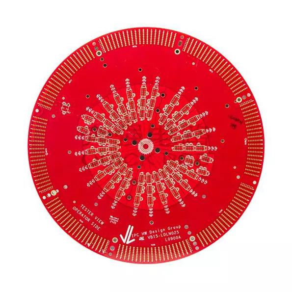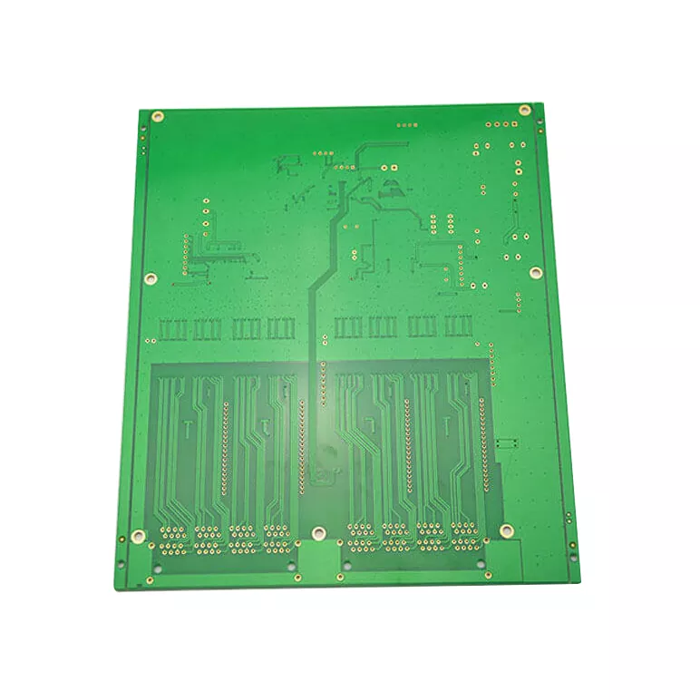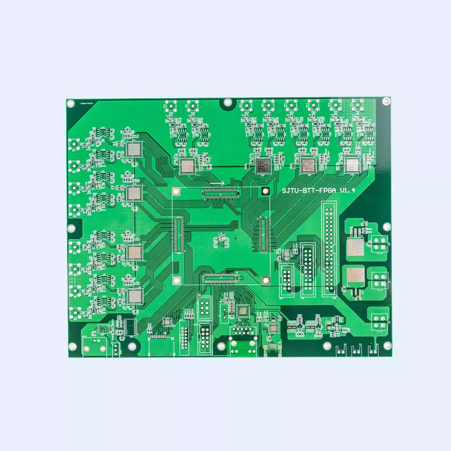

How Can an Electrical Muscle Stimulation Equipment PCB Improve Device Precision, Safety, and Reliability
Article Summary: An Electrical Muscle Stimulation Equipment PCB is the electronic foundation of an EMS device, coordinating pulse generation, current control, power management, and user interaction. For manufacturers developing rehabilitation equipment, sports recovery products, and wearable muscle stimulators, PCB design and manufacturing quality directly influence operational consistency and product integration. Aisen Electronics Co., Ltd. provides PCB fabrication and assembly solutions, including multilayer PCB and HDI technologies, to support the development of compact, reliable electronic products. This article explores essential design considerations, material selection, manufacturing processes, quality inspection, and supplier evaluation for EMS PCB projects.
Table of Contents
1. What Is an Electrical Muscle Stimulation Equipment PCB?
2. What Functions Does an EMS PCB Need to Perform?
3. Which PCB Design Factors Matter Most?
4. How Should Manufacturers Select PCB Materials and Structures?
5. How Is an EMS PCB Manufactured?
6. How Can PCB Quality and Reliability Be Verified?
7. Which Applications Benefit from Specialized EMS PCBs?
8. How Should You Choose an EMS PCB Manufacturing Partner?
1. What Is an Electrical Muscle Stimulation Equipment PCB?
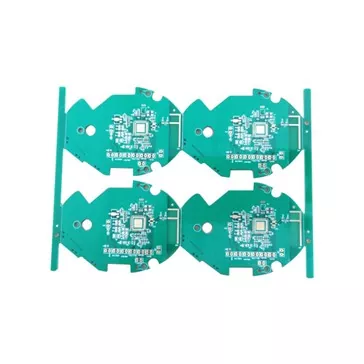
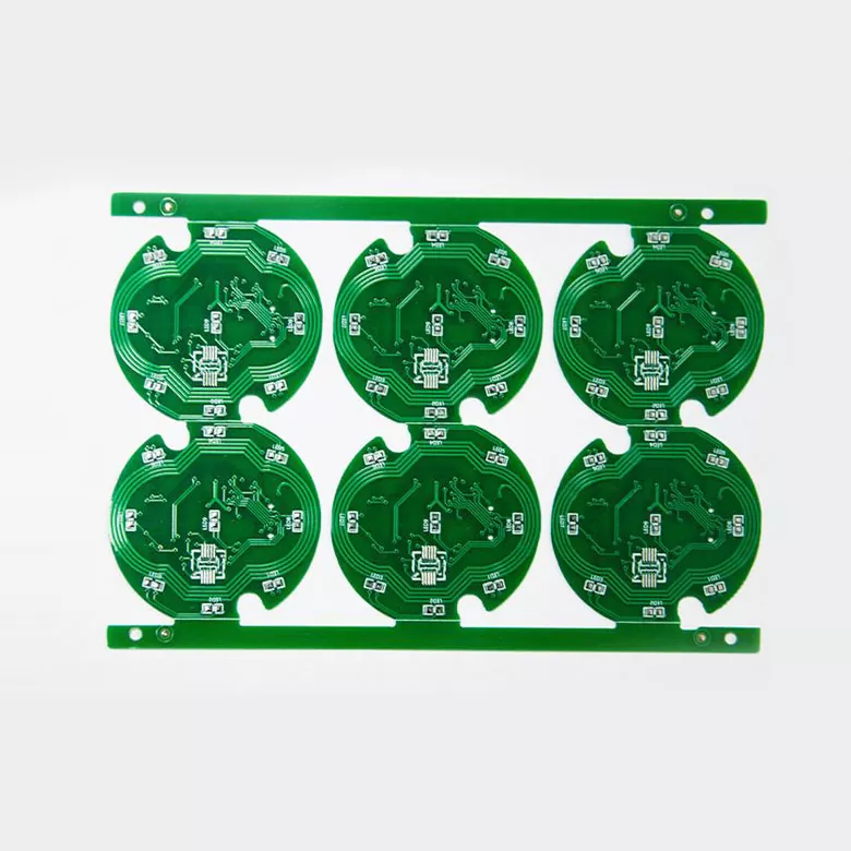
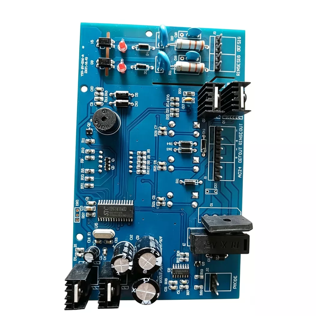
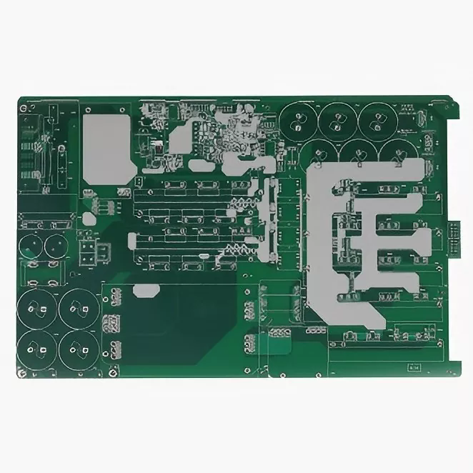
An Electrical Muscle Stimulation Equipment PCB is a printed circuit board designed to support the electronic functions of equipment that delivers controlled electrical pulses through electrodes. Depending on the product architecture, the board may integrate a microcontroller, pulse-generation circuitry, output drivers, power-management components, user-interface connections, and communication modules.
Unlike a basic electronic control board, an EMS PCB must support a carefully coordinated relationship between digital commands and stimulation output. The design needs to accommodate the device's intended pulse characteristics, operating conditions, electrical protection strategy, and physical dimensions.
For equipment manufacturers, the PCB is not simply a component carrier. It is a central part of the system that translates programmed settings into controlled electronic behavior.
Aisen Electronics Co., Ltd. manufactures Electrical Muscle Stimulation Equipment PCB solutions for applications such as rehabilitation devices, fitness recovery products, and portable stimulation equipment. Its manufacturing capabilities include multilayer boards, HDI structures, and PCB assembly services tailored to project requirements.
2. What Functions Does an EMS PCB Need to Perform?
The electronic architecture of an EMS device depends on its intended application, output channels, power source, and control features. However, several functional areas are commonly considered during development.
Pulse Generation and Control
The control circuit coordinates pulse timing and operating modes. Depending on the design, a microcontroller and associated driver circuitry generate the commands required to produce the specified stimulation waveform. Consistent timing and predictable circuit behavior are important for repeatable device operation.
Power Management
Portable EMS equipment may operate using rechargeable batteries or other low-voltage power sources. Power-management circuitry supports voltage regulation, charging functions where applicable, and stable operation across expected battery conditions.
Output Regulation and Protection
The output stage delivers electrical stimulation according to the device's specified operating parameters. Depending on the design, it may incorporate current regulation, output monitoring, fault detection, and protective circuitry. These functions should be developed and validated against the product's electrical safety requirements.
User Interface and Connectivity
Buttons, displays, indicators, and wireless communication modules can connect the control board to the user interface. Compact PCB layouts help integrate these functions while maintaining appropriate separation between sensitive signals and higher-energy output circuitry.
- Control: Coordinates operating modes and pulse timing.
- Power: Supports regulated supply and energy management.
- Output: Implements the specified stimulation waveform and output behavior.
- Monitoring: Supports fault detection and operating-status feedback when required.
- Connectivity: Integrates controls, displays, and communication functions as needed.
3. Which PCB Design Factors Matter Most?
Successful EMS PCB development requires coordinated electrical, mechanical, and manufacturing decisions. The following factors deserve particular attention during schematic review and PCB layout.
Signal Integrity and Circuit Separation
Digital control signals, switching power circuits, and stimulation output paths can interact through unwanted coupling. Component placement, return-current paths, grounding strategy, and routing geometry should be planned to minimize interference and maintain predictable circuit behavior.
Current Paths and Thermal Performance
Trace width, copper thickness, connector ratings, and component selection must reflect the actual electrical loads. Engineers should evaluate temperature rise and power dissipation under representative operating conditions rather than relying on general PCB rules alone.
Compact Layout and Component Density
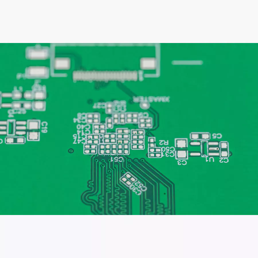
Wearable and handheld stimulators often have strict space constraints. Multilayer PCB construction and HDI technology can help accommodate fine-pitch components and dense interconnections. However, higher circuit density must remain compatible with assembly yield, inspection access, and repair requirements.
Electrical Protection and Patient Safety
EMS equipment intended for contact with the human body requires application-specific safety engineering. Designers should evaluate output limits, abnormal operating conditions, insulation requirements, and relevant electrical safety standards. PCB layout supports these measures but cannot independently establish the safety or regulatory compliance of the complete device.
For applicable nerve and muscle stimulators, manufacturers should assess the relevant requirements of IEC 60601-1 and IEC 60601-2-10, together with other standards applicable to the product's intended use and market.
4. How Should Manufacturers Select PCB Materials and Structures?
PCB materials and layer structures affect electrical performance, mechanical dimensions, manufacturability, and cost. The best choice depends on the device's circuit complexity, enclosure design, production volume, and reliability targets.
| PCB Option | Typical Application Consideration | Potential Benefit |
|---|---|---|
| Two-layer PCB | Relatively simple control circuits | Straightforward construction and cost management |
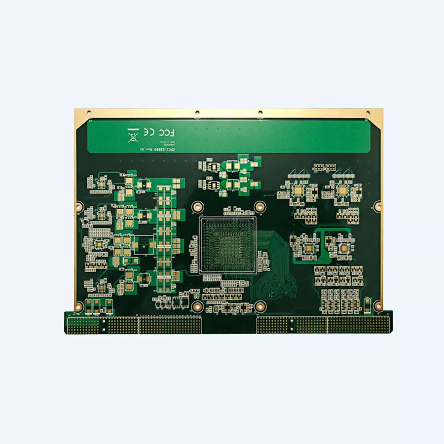
| Multilayer PCB | Integrated control, power, and communication functions | More routing options and improved layout organization |
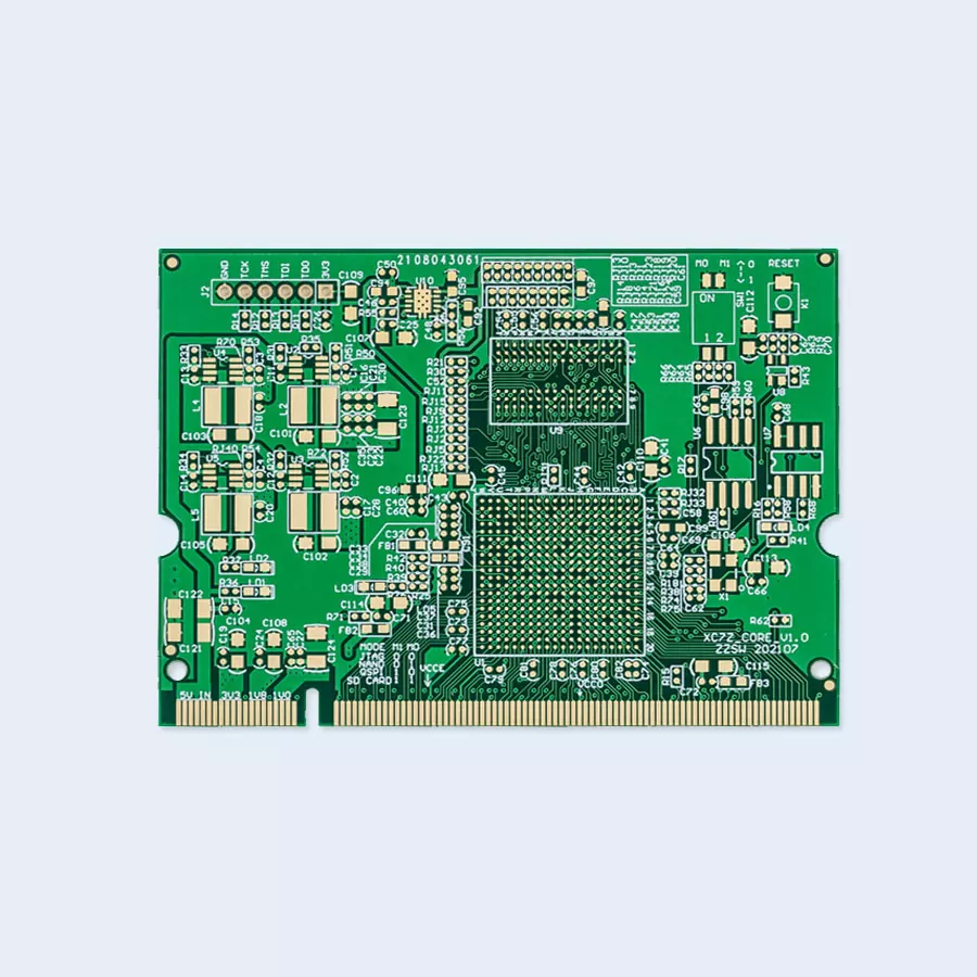
| HDI PCB | Compact products with dense component placement | Fine routing and efficient use of board space |
| Flexible PCB | Selected space-constrained or moving interconnections | Flexible routing between electronic assemblies |
| Rigid-flex PCB | Products requiring integrated rigid and flexible sections | Potential reduction in connectors and assembly space |
FR-4 is a common substrate for conventional rigid boards. Other materials may be considered when the design requires specific thermal, mechanical, or electrical characteristics. Material selection should be based on verified requirements rather than assuming that a more advanced substrate automatically delivers better performance.
Surface finish also matters. Electroless nickel immersion gold (ENIG), organic solderability preservative (OSP), lead-free hot air solder leveling (HASL), and immersion tin or silver may be considered according to component pitch, assembly conditions, shelf-life requirements, and budget.
According to its published product information, Aisen supports PCB manufacturing capabilities including:
- PCB structures ranging from 1 to 32 layers.
- Minimum line width and spacing of 3/3 mil, subject to design conditions.
- Board thickness from 0.3 mm to 5.0 mm.
- Copper thickness up to 6 oz.
- Minimum laser via diameter of 0.1 mm.
- Impedance control of ±8% where specified and applicable.
- HDI structures including 1+N+1 and 2+N+2.
These are published manufacturing capabilities, not universal recommendations or guaranteed specifications for every EMS project. Final feasibility should be confirmed through engineering review.
5. How Is an EMS PCB Manufactured?
A controlled manufacturing workflow helps transform an approved circuit design into a repeatable physical product. The exact process depends on board construction, layer count, material selection, and assembly requirements.
- Engineering review: Review Gerber files, drill data, stack-up, component constraints, and manufacturing specifications.
- Material inspection: Verify incoming materials against the approved project requirements.
- Inner-layer processing: Form and inspect circuit patterns for multilayer board construction.
- Lamination and drilling: Align and laminate layers, then create the required mechanical and interconnection holes.
- Plating and outer-layer formation: Establish electrical connections and form the external circuit patterns.
- Solder mask and surface finish: Apply the selected protective coating and final surface treatment.
- Inspection and electrical testing: Check circuit features and verify electrical connectivity against the approved criteria.
- PCB assembly: Where required, mount electronic components using SMT, through-hole, or mixed-technology processes.
- Functional verification: Conduct the agreed tests on the assembled board or complete device.
For EMS products, the manufacturing plan should address both bare-board quality and assembled-board performance. A visually acceptable PCB does not automatically confirm that pulse-generation circuits, power-management functions, or fault-monitoring features operate correctly.
6. How Can PCB Quality and Reliability Be Verified?
Quality verification should be planned before production begins. Clear acceptance criteria help manufacturers identify defects consistently and provide customers with evidence that the delivered boards meet agreed requirements.
| Inspection or Test | Main Purpose | Project Consideration |
|---|---|---|
| IQC | Incoming quality control | Check materials and components against specifications |
| AOI | Automated optical inspection | Identify visible pattern and assembly defects within inspection coverage |
| Electrical testing | Verify circuit connectivity | Detect opens, shorts, or other defined electrical faults |
| IPQC | In-process quality control | Monitor manufacturing steps and process consistency |
| FQC and OQC | Final and outgoing quality control | Confirm the product meets agreed delivery criteria |
| Functional testing | Verify intended electronic behavior | Check the specified functions under controlled test conditions |
EMS-specific functional testing may include:
- Verification of programmed operating modes and pulse timing.
- Measurement of output characteristics against approved test limits.
- Assessment of output behavior under representative electrical loads.
- Verification of power-management and charging functions where applicable.
- Testing of defined fault responses and protective functions.
- Inspection of solder joints, connectors, and critical components.
Electrical stimulation products require particular care because a board-level defect can affect the behavior of the complete device. Manufacturers should establish test methods using approved specifications and suitable measurement equipment. Final safety validation, clinical assessment where applicable, and regulatory approval remain separate activities that must be addressed for the finished product.
7. Which Applications Benefit from Specialized EMS PCBs?
An Electrical Muscle Stimulation Equipment PCB can support different product architectures, from basic portable stimulators to connected rehabilitation systems. Requirements vary according to the intended use and operating environment.
| Application | Typical Electronic Priorities |
|---|---|
| Portable muscle stimulators | Low power consumption, compact layout, and clear user controls |
| Rehabilitation equipment | Repeatable control behavior and application-specific safety verification |
| Sports recovery devices | Compact integration, mode selection, and consistent output behavior |
| Wearable EMS products | Space efficiency, battery integration, and suitable interconnections |
| Connected wellness equipment | Microcontroller integration and compatibility with communication modules |
For compact products, multilayer and HDI designs can help integrate more functions within a limited enclosure. Flexible circuits may also be suitable when the mechanical layout requires interconnections that cannot be accommodated efficiently by a rigid board.
Regardless of the application, PCB features should be selected according to documented functional requirements rather than assuming that every EMS product needs the same circuit architecture.
8. How Should You Choose an EMS PCB Manufacturing Partner?
Selecting a manufacturing partner involves more than comparing the quoted price per board. Engineering communication, process capability, assembly support, testing arrangements, and documentation can all influence project cost and delivery reliability.
Before placing an order, buyers should evaluate the following points:
- Manufacturing capability: Confirm the supplier can meet the required layer count, minimum feature sizes, board thickness, copper weight, and via structure.
- Assembly capability: Determine whether SMT, through-hole assembly, fine-pitch placement, and other required processes are available.
- Engineering support: Ask whether design-for-manufacturing and design-for-testing reviews are available before production.
- Quality procedures: Confirm which inspections and electrical tests are included in the quotation.
- Traceability: Establish expectations for material records, lot identification, inspection results, and change control.
- Production scalability: Discuss prototype quantities, pilot runs, forecast volumes, and repeat-order requirements.
- Commercial transparency: Review tooling charges, component sourcing, lead times, testing costs, and packaging requirements.
Aisen Electronics provides PCB fabrication and PCBA services, with published capabilities covering multilayer construction, HDI technology, fine-line routing, and electronic assembly. Buyers developing an EMS product can use these capabilities as a starting point for a technical feasibility discussion.
For a more efficient quotation process, prepare a complete project package containing the Gerber files, bill of materials (BOM), assembly drawings, stack-up requirements, target quantity, and functional testing expectations. Where available, include the intended operating conditions and relevant safety requirements.
For further details, visit the Aisen Electrical Muscle Stimulation Equipment PCB product page or explore its PCB manufacturing website.
9. Frequently Asked Questions
What is the main purpose of an Electrical Muscle Stimulation Equipment PCB?
Its main purpose is to support the electronic control and delivery of specified stimulation signals. Depending on the design, it also manages power, user inputs, communication functions, and monitoring or protection circuits.
How many PCB layers does an EMS device need?
The required layer count depends on circuit complexity, board dimensions, signal routing, and component density. A relatively simple product may use a two-layer board, while compact or functionally integrated equipment may benefit from a multilayer or HDI structure. The final stack-up should be determined through engineering review.
Why is PCB layout important for EMS equipment?
PCB layout influences signal interference, current distribution, thermal performance, and the separation of sensitive control circuitry from output and power sections. A carefully reviewed layout supports predictable operation and facilitates safety verification of the finished device.
Can Aisen manufacture compact EMS PCBs?
Aisen's published manufacturing capabilities include multilayer PCB fabrication, HDI structures, and fine-line routing for compact electronic designs. The feasibility of a particular board depends on its dimensions, stack-up, material requirements, and design files.
Does Aisen provide PCB assembly services?
Yes. Aisen lists PCB assembly services that include SMT component placement, electronic component assembly, functional testing, and production support. The specific assembly scope and testing arrangements should be confirmed for each project.
What files are needed to request an EMS PCB quotation?
Typical quotation documents include Gerber files, drill files, a PCB stack-up or fabrication drawing, BOM, assembly drawings, component placement data, and the required production quantity. Test specifications and any special material or inspection requirements should also be provided when applicable.
How can manufacturers evaluate EMS PCB reliability?
Reliability evaluation combines appropriate material selection, design review, controlled fabrication, assembly inspection, electrical testing, and functional verification. For the complete device, additional testing must address applicable electrical safety, electromagnetic compatibility, and regulatory requirements.
10. Conclusion
An Electrical Muscle Stimulation Equipment PCB plays a central role in coordinating electronic control, power management, and stimulation output. Choosing the right circuit structure, materials, manufacturing process, and inspection strategy helps product developers manage technical risks and achieve more consistent production results. Equally important are clear specifications, practical design-for-manufacturing reviews, and functional tests aligned with the intended device.
Aisen Electronics Co., Ltd. offers PCB manufacturing and assembly capabilities for companies developing rehabilitation equipment, fitness recovery products, and compact electronic devices. If you are planning a new EMS project or looking for a manufacturing partner for an existing design, contact us to discuss your PCB specifications, assembly requirements, and production goals. Share your design files and project expectations to start a focused technical discussion about a suitable manufacturing solution.
Related News
- How Can a Flow Rate And Dispensing Systems PCB Improve Fluid Measurement Accuracy and Equipment Reliability
- Is a Semiconductor Testing PCB the Weak Link in Your Test Setup
- How Can a Converter and Selector PCB Improve Electronic Control, Reliability, and Design Flexibility
- How Can Industrial Control Instruments PCB Improve Reliability, Signal Accuracy, and Long-Term Automation Performance
- Why Is an Electrical Measuring Instruments PCB Critical for Accurate and Reliable Measurement
- How Can a Communication Routers PCB Board Improve High-Speed Network Performance and Reliability
Leave me a message