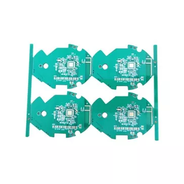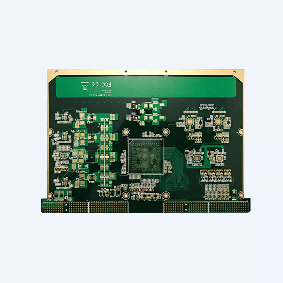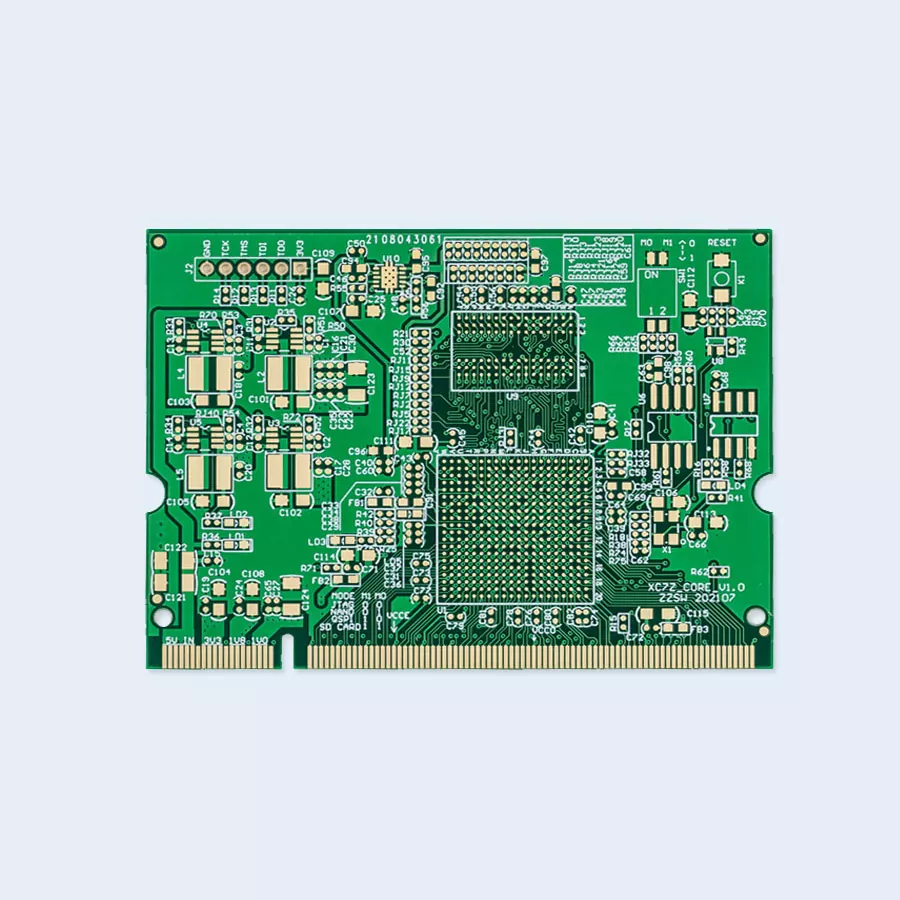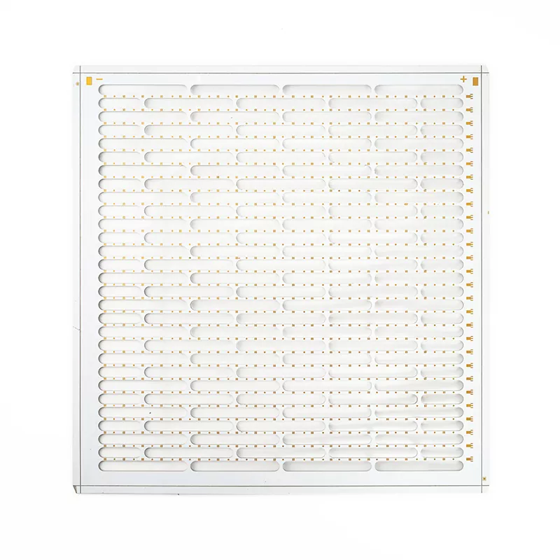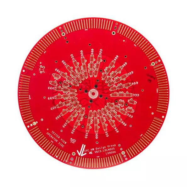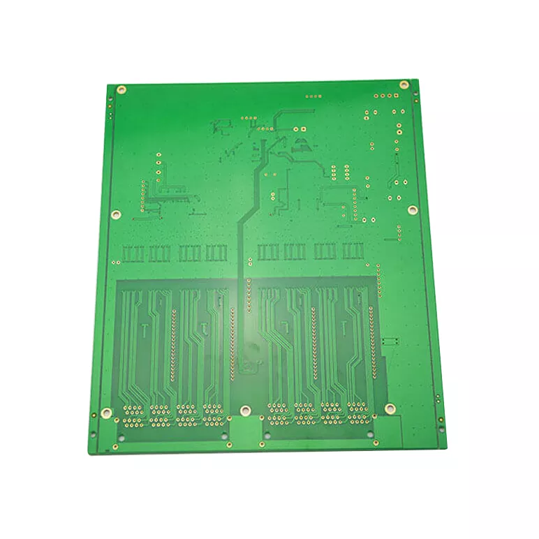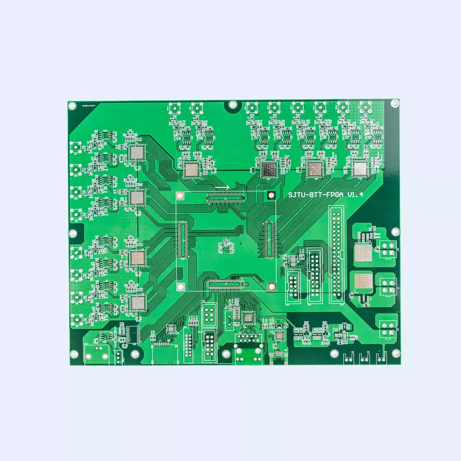

How Can a Flow Rate And Dispensing Systems PCB Improve Fluid Measurement Accuracy and Equipment Reliability
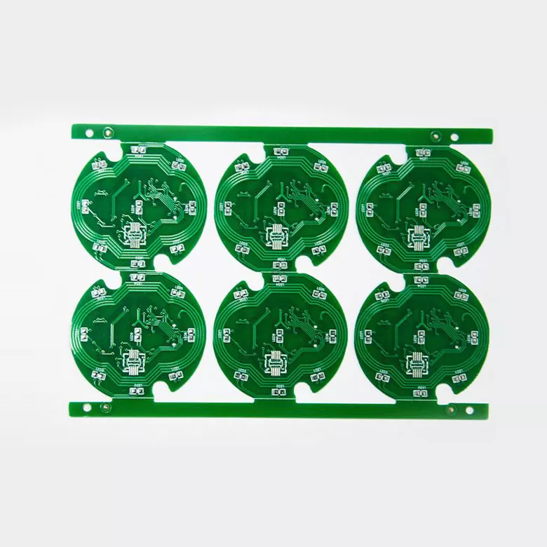
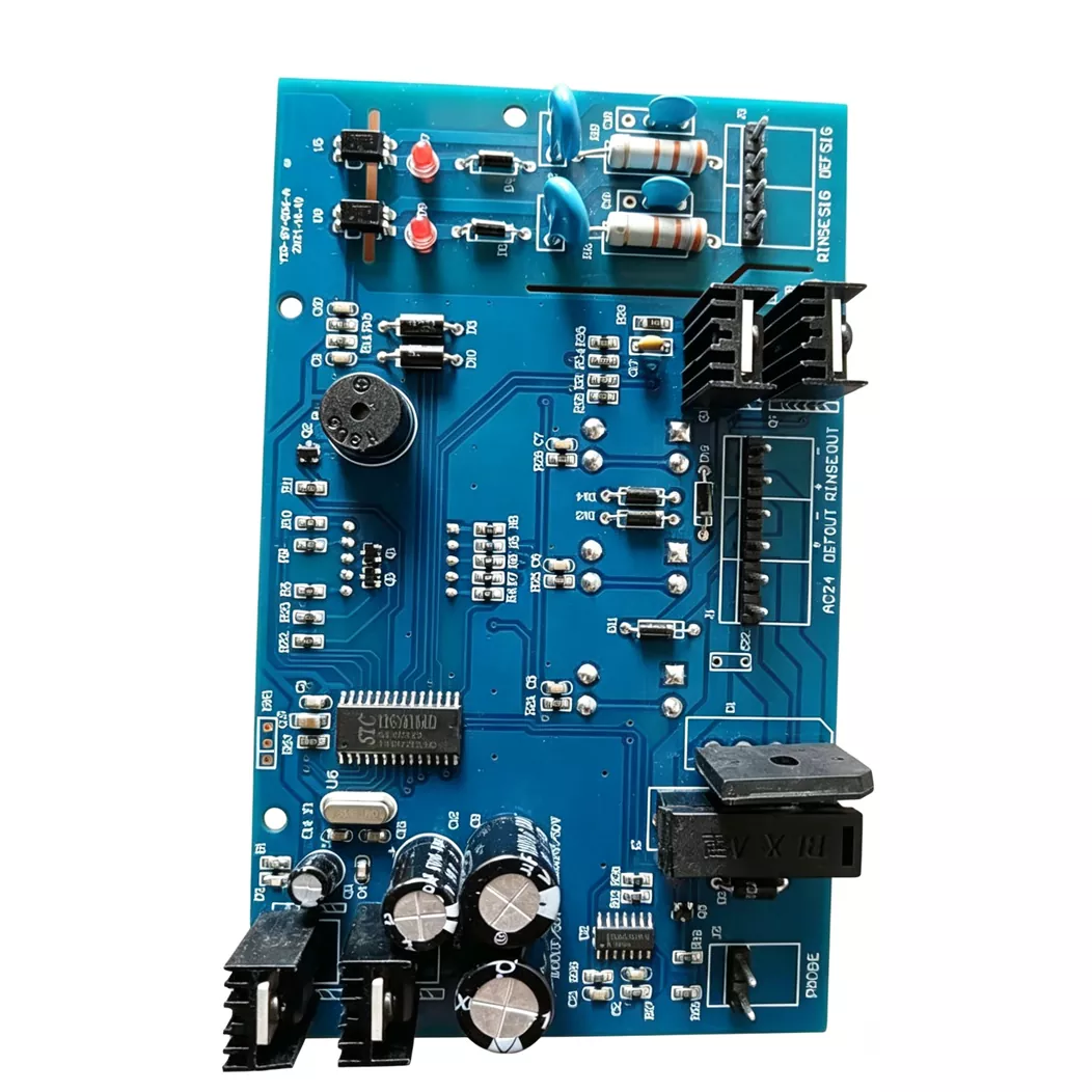
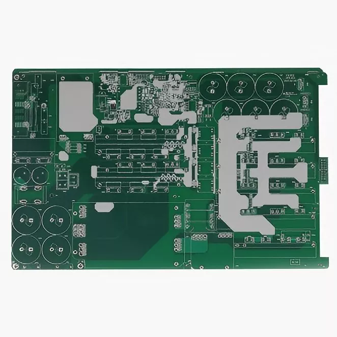
In modern industrial automation, medical instruments, and precision liquid handling equipment, accurate fluid measurement depends heavily on reliable electronic control. Aisen Electronics specializes in manufacturing the Flow Rate And Dispensing Systems PCB, providing customized circuit board solutions for flow meters, liquid dispensing machines, laboratory instruments, and industrial fluid control equipment. By integrating stable sensor signal processing, intelligent control circuits, and reliable electrical connections, these PCBs help equipment manufacturers achieve consistent measurement accuracy, repeatable dispensing performance, and dependable long-term operation.
A Flow Rate And Dispensing Systems PCB serves as the electronic foundation of modern fluid measurement and dispensing equipment. It connects flow sensors, microcontrollers, communication interfaces, pumps, and valves to transform measurement signals into accurate operating commands. This article explores its working principles, essential design considerations, PCB structure selection, industrial applications, manufacturing processes, and assembly requirements. It also explains how customized PCB solutions from Aisen Electronics can support equipment manufacturers seeking stable performance, compact integration, and reliable production quality.
Table of Contents
- 1. What Is the Role of a Flow Rate And Dispensing Systems PCB?
- 2. How Does a Flow Control PCB Work?
- 3. Key PCB Design Considerations for Accurate Fluid Control
- 4. Major Applications Across Different Industries
- 5. How to Select the Right PCB Structure
- 6. Technical Capabilities and Manufacturing Specifications
- 7. Manufacturing and Quality Control Requirements
- 8. Why PCB Assembly Matters for Dispensing Equipment
- 9. How to Choose a Reliable PCB Manufacturing Partner
- 10. Frequently Asked Questions
- 11. Conclusion: Building More Reliable Fluid Control Systems
1. What Is the Role of a Flow Rate And Dispensing Systems PCB?
A Flow Rate And Dispensing Systems PCB is a specialized printed circuit board designed to support electronic measurement, processing, and regulation of liquid or gas movement. It provides the electrical connections and control architecture needed to coordinate sensors, processors, communication modules, and mechanical actuators.
Unlike a conventional circuit board used primarily for basic electrical connections, a flow control PCB must support measurement accuracy and consistent control responses. Its design directly influences how effectively equipment detects fluid movement, calculates flow rates, and adjusts dispensing operations.
In a typical system, the PCB performs several important functions:
- Sensor signal acquisition: Receives electrical signals generated by flow sensors and other measurement components.
- Data processing: Converts sensor signals into usable measurement information through dedicated electronic circuits and microcontrollers.
- Flow regulation: Sends control signals to pumps, valves, and other actuators.
- Communication: Exchanges operating data with displays, industrial controllers, and external monitoring systems.
- Power management: Distributes stable electrical power to different electronic modules.
For liquid dispensing machines, these functions work together to ensure that each dispensing cycle delivers the intended quantity with consistent repeatability.
2. How Does a Flow Control PCB Work?
The working principle of a flow control PCB involves a continuous process of signal acquisition, electronic processing, and output regulation. The specific architecture depends on the flow sensor, dispensing mechanism, and control requirements of the equipment.
A typical operating process includes the following stages:
- Fluid detection: A flow sensor detects fluid movement and generates an electrical signal corresponding to the measured flow condition.
- Signal acquisition: The PCB receives the sensor output through an appropriate interface circuit.
- Signal conditioning: Filtering and signal conditioning circuits help reduce unwanted electrical noise and improve signal stability.
- Data calculation: A microcontroller or processing unit calculates flow-related information based on the incoming signals.
- Control execution: The PCB generates output commands for pumps, solenoid valves, motors, or other actuators.
- System feedback: Additional sensor information can be used to adjust operation and maintain the required dispensing conditions.
This feedback-based control architecture is particularly valuable in automated liquid filling systems, laboratory equipment, and industrial fluid management applications.
When the PCB has stable signal processing and carefully designed control circuits, the overall system can achieve more consistent operation and reduce measurement-related errors.
3. Key PCB Design Considerations for Accurate Fluid Control
Developing a reliable Flow Rate And Dispensing Systems PCB requires more than selecting suitable electronic components. Engineers must consider electrical performance, circuit layout, environmental conditions, and the physical requirements of the final equipment.
3.1 Signal Integrity and Electromagnetic Interference
Flow sensors may produce relatively weak electrical signals that are vulnerable to interference from nearby motors, switching power supplies, solenoid valves, and high-current circuits.
To improve signal integrity, PCB designers should consider:
- Separating sensitive analog signal paths from high-current switching circuits.
- Optimizing component placement and signal routing.
- Using appropriate filtering and shielding strategies where required.
- Designing suitable grounding and return-current paths.
3.2 Grounding and Power Distribution
Stable grounding is essential for measurement-based electronics. Poor grounding arrangements may introduce unwanted voltage fluctuations and measurement inconsistencies.
Engineers should evaluate ground plane configuration, power supply stability, decoupling capacitor placement, and the current requirements of individual circuit sections.
3.3 Component Layout and Thermal Management
The arrangement of sensors, processors, power devices, and communication interfaces influences both electrical performance and equipment integration.
Important considerations include:
- Maintaining appropriate spacing between sensitive and high-power components.
- Providing sufficient thermal management for power-related devices.
- Optimizing connector positions for convenient equipment installation.
- Considering mechanical vibration and enclosure limitations.
3.4 Environmental Protection
Industrial and automotive fluid control equipment may operate under humidity, temperature fluctuations, vibration, and electrical interference. Material selection, surface finishing, and protective coatings should therefore be evaluated according to the actual operating environment.
Aisen Electronics supports customized PCB layouts based on sensor types, communication protocols, equipment dimensions, and application-specific requirements.
4. Major Applications Across Different Industries
Flow measurement and dispensing electronics are used in a wide range of equipment. Different industries have different expectations regarding circuit stability, board dimensions, operating conditions, and manufacturing consistency.
4.1 Industrial Flow Monitoring Systems
Industrial flow monitoring equipment is commonly installed in manufacturing facilities, water treatment systems, energy infrastructure, and process automation lines.
These systems require PCBs capable of supporting:
- Continuous sensor data acquisition.
- Long operating cycles.
- Stable operation in electrically noisy environments.
- Consistent communication with industrial controllers.
- Reliable connections between sensors and control devices.
4.2 Medical and Laboratory Dispensing Equipment
Medical and laboratory instruments often require compact electronic designs and precise fluid handling. Applications include laboratory analyzers, automated liquid handling equipment, and infusion-related electronic systems.
For these applications, PCB design typically emphasizes:
- Compact circuit integration.
- Low-noise sensor interfaces.
- Accurate motor and valve control.
- Consistent assembly quality.
- Reliable electrical connections.
4.3 Automotive Fluid Management Systems
Automotive fluid control modules operate under challenging conditions, including vibration, temperature changes, and electromagnetic interference.
Potential applications include:
- Engine cooling system monitoring.
- Fuel management control.
- Hydraulic control modules.
- Automotive thermal management systems.
PCB materials, component selection, and mechanical design must be matched to the vehicle's operating environment and applicable reliability requirements.
5. How to Select the Right PCB Structure
The appropriate PCB structure depends on circuit complexity, signal requirements, component density, installation space, and the operating environment.
Different fluid control products may require different PCB configurations.
| Application Type | Recommended PCB Structure | Main Design Consideration |
|---|---|---|
| Basic Flow Sensor Module | Single-sided or double-sided PCB | Basic signal acquisition and compact design |
| Smart Flow Meter | 4-6 Layer PCB | Signal integrity and circuit integration |
| Industrial Control Unit | Multilayer PCB | Multiple interfaces and complex control functions |
| Integrated Dispensing System | HDI or Rigid-Flex PCB | High-density integration and installation flexibility |
For relatively simple flow sensor applications, a double-sided board may provide sufficient circuit space. More advanced systems with multiple sensor channels, communication modules, and control functions may benefit from multilayer PCB structures.
Rigid-flex PCB technology can also be considered when equipment requires three-dimensional installation or flexible connections between different electronic sections.
The final structure should always be determined through engineering evaluation rather than selecting the highest layer count by default.
6. Technical Capabilities and Manufacturing Specifications
PCB manufacturing capabilities are important when developing specialized flow measurement and dispensing equipment. A suitable manufacturing partner should be able to accommodate different board dimensions, layer counts, copper weights, and surface finishing requirements.
According to Aisen Electronics' published product information, its PCB manufacturing capabilities include the following specifications:
| Technical Parameter | Manufacturing Capability |
|---|---|
| Layer Count | 1-32 Layers |
| Minimum Line Width / Spacing | 3/3 mil |
| Board Thickness | 0.3-5.0 mm |
| Copper Thickness | Up to 6 OZ |
| Minimum Laser Via | 0.1 mm |
| Maximum Panel Size | 650 × 750 mm |
| Surface Treatment | ENIG, OSP, HASL, Immersion Silver, Immersion Tin |
These manufacturing options support different electronic design requirements, from compact sensor interface boards to more complex industrial control platforms.
For example, a high-density dispensing controller may require multilayer routing and smaller vias, while an industrial flow monitoring board may prioritize appropriate copper thickness and reliable electrical connections.
Engineers should confirm the specific production requirements and design feasibility with the PCB manufacturer before finalizing the board layout.
7. Manufacturing and Quality Control Requirements
Manufacturing consistency is especially important for measurement-based electronics. Variations in circuit integrity, solderability, or electrical connections may affect the stability of the final equipment.
A reliable Flow Rate And Dispensing Systems PCB manufacturing process should include several essential stages.
7.1 Material Verification
Base materials and copper-clad laminates should be checked against the approved design specifications. Material selection should reflect the board's electrical, thermal, and environmental requirements.
7.2 Circuit Layer Alignment
For multilayer boards, accurate alignment between circuit layers is necessary to maintain the intended electrical connections and structural consistency.
7.3 Precision Drilling and Copper Plating
Drilling and plating processes establish electrical connections between different PCB layers. Process control is essential for maintaining reliable via structures and conductive pathways.
7.4 Surface Finishing
Surface treatments such as ENIG, OSP, HASL, immersion silver, and immersion tin are selected according to component assembly requirements, solderability, and application conditions.
7.5 Electrical Testing
Electrical testing helps identify open circuits, short circuits, and other manufacturing defects before the boards proceed to assembly or delivery.
At Aisen Electronics, key manufacturing stages include:
- Raw material verification.
- Precision circuit fabrication.
- Layer alignment and drilling control.
- Copper plating process control.
- Surface finishing inspection.
- Electrical testing and production verification.
These manufacturing controls help support consistent PCB quality for applications where stable electrical performance is essential.
8. Why PCB Assembly Matters for Dispensing Equipment
For many equipment manufacturers, bare PCB fabrication is only one part of the electronics production process. A complete electronic assembly may also require component sourcing, SMT placement, soldering, inspection, and functional verification.
PCB assembly transforms the fabricated board into an operational electronic module.
Aisen Electronics provides PCBA-related services for flow control applications, including:
- SMT Assembly: Surface-mount component placement for compact and integrated circuit designs.
- Sensor Interface Assembly: Integration of electronic interfaces for different flow sensor configurations.
- Microcontroller Installation: Assembly of processing components used for measurement and control operations.
- Functional Testing: Testing support to evaluate assembly and electronic functionality.
- Production Support: Manufacturing coordination for customized electronic assemblies.
Combining PCB fabrication and assembly can simplify supplier coordination and improve communication between design and production teams.
For equipment developers, this integrated approach can be especially useful when transitioning from prototype development to repeat production.
9. How to Choose a Reliable PCB Manufacturing Partner
Selecting a PCB manufacturer is an important decision for companies developing fluid measurement and dispensing equipment. Beyond unit pricing, buyers should evaluate manufacturing capability, engineering communication, quality management, and long-term production support.
The following checklist can help procurement teams and hardware engineers evaluate potential suppliers.
| Evaluation Factor | What Buyers Should Check | Why It Matters |
|---|---|---|
| Manufacturing Capability | Layer count, line width, copper thickness, and board dimensions | Ensures design compatibility |
| Engineering Support | PCB layout review and DFM communication | Helps identify production risks |
| Quality Control | Material checks and electrical testing | Supports consistent product quality |
| Assembly Services | SMT, component integration, and functional testing | Simplifies production coordination |
| Customization | Support for different structures and specifications | Matches application-specific requirements |
| Communication | Technical response and production updates | Improves project coordination |
Before placing an order, buyers should prepare the following information:
- PCB Gerber files and fabrication drawings.
- Board dimensions and required layer count.
- Material and copper thickness specifications.
- Surface finish requirements.
- Expected production quantity.
- Component BOM and assembly drawings, if PCBA is required.
- Testing requirements and expected operating conditions.
Providing complete technical documentation helps the manufacturer evaluate the project more efficiently and recommend an appropriate production solution.
10. Frequently Asked Questions
Q1: What is a Flow Rate And Dispensing Systems PCB used for?
A Flow Rate And Dispensing Systems PCB is used to manage electronic functions in fluid measurement and dispensing equipment. It connects flow sensors, processing units, communication interfaces, and actuators to support accurate measurement and controlled fluid delivery.
Q2: What types of sensors can be connected to a flow control PCB?
Depending on the equipment design, a flow control PCB can support different sensor interfaces, including pulse-output, analog-output, and digital communication-based sensors. The specific interface depends on sensor electrical characteristics and system requirements.
Q3: Why is signal integrity important in dispensing system PCBs?
Signal integrity is important because unstable sensor signals may result in incorrect measurement calculations or inconsistent control responses. Proper grounding, signal routing, filtering, and component placement help reduce electrical interference and improve measurement stability.
Q4: Which PCB layer count is suitable for a smart flow meter?
A smart flow meter may use a 4-6 layer PCB when its design includes multiple sensor channels, microcontrollers, communication interfaces, and power management circuits. However, the final layer count should be determined by routing complexity, board dimensions, and electrical requirements.
Q5: Can Flow Rate And Dispensing Systems PCB be customized?
Yes. PCB designs can be customized according to board dimensions, layer count, copper thickness, sensor interfaces, component placement, communication protocols, and environmental requirements. Aisen Electronics supports customized manufacturing for different flow measurement and dispensing applications.
Q6: Does Aisen Electronics provide PCB assembly services?
Yes. Aisen Electronics provides PCB fabrication and PCBA-related services, including SMT assembly, sensor interface assembly, microcontroller installation, functional testing, and production support.
Q7: What surface finishes are available for flow control PCBs?
Available manufacturing options published by Aisen Electronics include ENIG, OSP, HASL, immersion silver, and immersion tin. The appropriate finish depends on solderability requirements, component selection, storage conditions, and the intended application.
Q8: What information should I provide when requesting a PCB quotation?
Buyers should provide Gerber files, board dimensions, layer count, copper thickness, material requirements, surface finish, estimated order quantity, and any special electrical or environmental specifications. For assembly projects, a BOM and assembly drawings are also recommended.
11. Conclusion: Building More Reliable Fluid Control Systems
A well-designed Flow Rate And Dispensing Systems PCB is essential for achieving accurate measurement, stable signal processing, and reliable dispensing control. From industrial flow monitoring and laboratory instruments to automotive fluid management systems, the right PCB structure and manufacturing process help equipment developers meet increasingly demanding electronic integration requirements.
Choosing an experienced manufacturing partner is equally important. With capabilities covering 1-32 layer PCB production, fine-line fabrication, multiple surface finishing options, and PCBA services, Aisen Electronics supports customized electronic manufacturing requirements for different flow control applications. Whether you are developing a compact sensor interface, an intelligent flow meter, or a complex liquid dispensing controller, selecting the right manufacturing solution can help improve product consistency and simplify production management.
Looking for a dependable manufacturing partner for your next fluid control electronics project? Aisen Electronics is ready to support your PCB and PCBA requirements with customized manufacturing solutions and professional project communication. Share your design files, technical specifications, and production expectations with our team today. Explore our Flow Rate And Dispensing Systems PCB solutions or contact us to discuss your project and request a customized quotation.
Related News
- How Can an Electrical Muscle Stimulation Equipment PCB Improve Device Precision, Safety, and Reliability
- Is a Semiconductor Testing PCB the Weak Link in Your Test Setup
- How Can a Converter and Selector PCB Improve Electronic Control, Reliability, and Design Flexibility
- How Can Industrial Control Instruments PCB Improve Reliability, Signal Accuracy, and Long-Term Automation Performance
- Why Is an Electrical Measuring Instruments PCB Critical for Accurate and Reliable Measurement
- How Can a Communication Routers PCB Board Improve High-Speed Network Performance and Reliability
Leave me a message